Place Timber Floor/Roof Joists at a Spacing
 Used to place timber floor
and roof joists at specified intervals.
Used to place timber floor
and roof joists at specified intervals.
Placement tab

| Setting | Description |
|---|---|
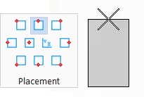
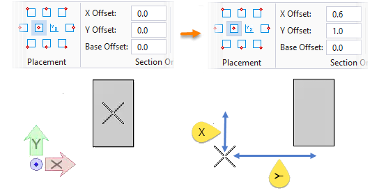
| Placement | Defines the location of the baseline relative to the member section by selecting from the drop list items. The attachment point dynamically updates on the pointer as the Placement icons are selected. |
| Offsets: |
|
| Aligned | When on, aligns the new members with existing members. The rotation angle for each new member is derived from the first supporting member’s member line (or the tangent to the curve at the intersection point if the supporting member is a curved member). The current Rotation angle value is added to the derived rotation. |
| Mirror | Typically used for member sections whose axis is not symmetric about its Y axis (for example, angles, channels, or zees). When on, an identical member is constructed, but in a mirror-image/flipped orientation. When off, mirroring already applied is removed. |
| Rotation: |
Entered directly or selected from a drop down list
of common angles between minus 180° and plus 180°.
Note: The specific
entries are defined in the
Design File Settings Dialog's
Locks settings category.
|
 Automatic End Trim Automatic End Trim
|
When on, enables automatic trimming as concrete/timber members are placed connected to other concrete/timber members. When off, the Trim Options are also disabled. |
 Trim to member connected by
AccuSnap Trim to member connected by
AccuSnap
|
Fits the member around the selected connecting member |
 Trim to any interfering member Trim to any interfering member
|
Fits the member around all members in the vicinity of the member end. |
| Number Of Members | Places the number of members entered in the value field with equal spacing. |
| Maximum Spacing | Places members using the entered value as the maximum space allowed. Members are placed evenly without exceeding the value. |
| Absolute Spacing | Places members using the absolute or exact value entered. The remainder space is left at the end of the support farthest from the pick point used to identify it. |
| End Members | When on, two additional members are placed connecting the ends of the supporting members. |
| Perpendicular To Support | When on, members are placed perpendicular to the first supporting member selected. |
| Support Options | Three options to control which line of the support for elements to be used. |

Timber Floor/Roof Joists at Spacing Properties

| Setting | Description |
|---|---|
| Catalog Type Selector | Used to select from available Catalog Types. Selections made here updates the Catalog Item Selector combo box. |
| Catalog Item Selector |
Used to select from available
Catalog Items. The
Catalog Item Selector combo box contains
several options and settings designed to make it easier to find the exact
catalog item you need to place/change.
The
Catalog Item list also includes user
defined assemblies, and RFA catalog items, if any.
|
| Catalog Tools |
A split button located to the right of the
Catalog Item Selector contains tools to
assist with managing catalog data prior to placement of selected catalog items.
Note: The
Save Catalog Item and
Save Catalog Item As... tools perform
administrative tasks on DataGroup System catalogs. Administrators and users may
want to hide the tool icons to avoid incidental or unwanted changes to their
firm's dataset by setting the user configuration variables
BB_CATALOGITEM_ADMIN_IN_PLACECMDS
and
BB_CATALOGITEM_SAVEAS_IN_PLACECMDS to "0", respectively.
|
| Preview |
Displays the selected catalog item in the preview
window. This display changes and the preview updates as various options are
chosen. The preview also changes dynamically with some of the
prominent settings on the Placement tab, e.g Height, Rotation angle, etc. A
right-click in the Preview opens a
Show/Hide Viewing Tools option menu:
|
| Properties list - toolbar |
Used to manage catalog item properties during
placement or modification. Catalog item properties define the catalog item
instance in the model, and are accountable in the DataGroup System data
management tools. You can place a catalog item with its default property values
or you can change property values as needed, place an instance in the model,
and optionally save the changes to the catalog.
The Properties combo box contains tools for sorting and searching the properties list:
|
| Structural Parameters |
|
| Structural Usage | Lists Structural usage properties. Structural function and material properties can be applied (if undefined) to active catalog items making them fully promoted Structural members. |
| Materials |
|
| Identification | Lists identification properties for the active catalog item type. |
| Fire Resistance | Lists fire rating properties based on agency fire safety tests and classifications. |
| Thermal Transmittance | Lists the thermal properties to apply to the active catalog item. |
| Construction Phase | Lists design and construction phase properties for walls such as New Construction, Future Construction, and Items to be Moved. |
| IFC Override | Lists IFC properties not automatically mapped to DataGroup System properties that can be manipulated for export. |
| LEED Parameters | Lists several common Leadership in Energy and Environmental Design properties used to identify compliance of the active catalog item. |
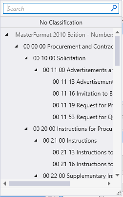
| Classification | Building Classification Systems are supported by the DataGroup System. MasterFormat, OmniClass, and UniFormat property values can be associated with any Building element. Click the Value cell to open the Classification System selection combo box. The combo box is populated with selected classification system property values. It can be resized by clicking on the combo box's bottom right corner. Search for properties by name. Search results are displayed in the classifications hierarchy. Double click a property to select it. This action also closes the selection menu. The selected property displays in the selected classification system property value (on the Properties list). |
| Structural Data |
|

 (
( (
( (
( (
( (
( (
( (
( (
( (
(


 (
( (
( (
(